


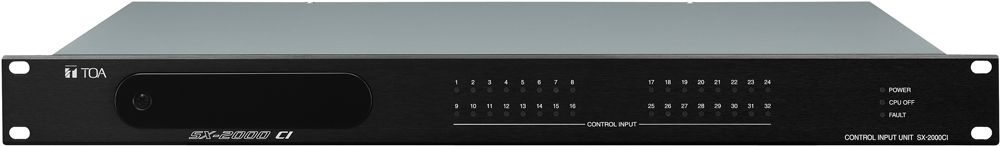
SX-2000CI
The SX-2000CI is a control input of the matrix system and can be mounted in an EIA equipment rack (1 U size). Multiple units can be decentralized in a whole system. It is equipped with 32 control input channels. Control input line failure can be detected by connecting resistors to its line. The indicators on the front panel monitor the control input line status. The SX-2000CI has a function to supply a stabilized 24 V DC. The SX-2000CI has two power inputs and can support a dual-redundant power supply system. By using a stand-alone mode, system can be configured with only the SX-2000CI, SX-2000CO Control output unit and the power supply unit, permitting the contact data of multiple channels to be transmitted to the remote locations with simple wiring.


| Power Source | Usable power supply unit: VX-200PS 24 V DC (operational range: 20 V - 40 V DC) Two power inputs construction enables dual-redundant power supply. |
|---|---|
| Current Consumption | 0.7 A or less (maximum value in the power operating range) 0.55 A or less (when operated on 24 V DC) |
| Indication | Control input indicator (32), Power indicator, CPU OFF indicator, FAULT indicator |
| Control Input | 32 inputs, no-voltage make contact input, open voltage: 24 V DC, short-circuit current: 2 mA, photo coupler input, removable terminal block (16 pins) |
| Surveillance Section for The Control Input Lines | Connection resistance to make the function inactive: 20 kΩ ±5 % Connection resistance to make the function active: 10 kΩ ±5 % Connector cable: Twisted pair cable (shielded type is recommended) Maximum cable distance: 10 m (32.81 ft) |
CI/CO Link
| Input/Output Connector | Input: 1 input, Output: 1 output RJ45 Connector |
|---|---|
| Connection Cable | Shielded Category 5 twisted pair cable (CAT5-STP) (1 pair of data wire + 1 pair of control wire) |
| Maximum Cable Distance | 800 m (874.89 yd) |
24 V DC Output
| Output Voltage | 24 V DC ±10 % or less |
|---|---|
| Maximum Feeding Current | 100 mA |
| Connector | Removable terminal block (2 pins) |
| Operating Temperature | 0 ℃ to +40 ℃ (32 ゜F to 104 ゜F) |
|---|---|
| Operating Humidity | 35 % to 80 %RH (no condensation) |
| Finish | Panel: Aluminum, black, alumite Case: Surface-treated steel plate |
| Dimensions | 482 (W) × 44 (H) × 331.5 (D) mm (18.98 × 1.73" × 13.05")" |
| Weight | 3.6 kg (7.94 lb) |
| Accessory | Removable terminal plug (16 pins) …4, Removable terminal plug (4 pins) …1, Removable terminal plug (2 pins) …1, Rack mounting screw …4 |
When operating in matrix mode
| Power Source | Usable power supply unit: AD-011, AD-031B 24 V DC (operational range: 20 V - 40 V DC) Two power inputs construction enables dual-redundant power supply. |
|---|---|
| Current Consumption | 0.7 A or less (maximum value in the power operating range) 0.55 A or less (when operated on 24 V DC) |
| Indication | Control input indicator (32), Power indicator, CPU OFF indicator, FAULT indicator |
| Control Input | 32 inputs, no-voltage make contact input, open voltage: 24 V DC, short-circuit current: 2 mA, photo coupler input, removable terminal block (16 pins) |
| Surveillance Section for The Control Input Lines | Connection resistance to make the function inactive: 20 kΩ ±5 % Connection resistance to make the function active: 10 kΩ ±5 % Connector cable: Twisted pair cable (shielded type is recommended) Maximum cable distance: 10 m (32.81 ft) |
CI/CO Link
| Input/Output Connector | Input: 1 input, Output: 1 output RJ45 Connector |
|---|---|
| Connection Cable | Shielded Category 5 twisted pair cable (CAT5-STP) (1 pair of data wire + 1 pair of control wire) |
| Maximum Cable Distance | 800 m (874.89 yd) |
| Output Voltage | 24 V DC ±10 % or less |
|---|---|
| Maximum Feeding Current | 100 mA |
| Connector | Removable terminal block (2 pins) |
| Operating Temperature | 0 ℃ to +40 ℃ (32 ゜F to 104 ゜F) |
|---|---|
| Operating Humidity | 35 % to 80 %RH (no condensation) |
| Finish | Panel: Aluminum, black, alumite Case: Surface-treated steel plate |
| Dimensions | 482 (W) × 44 (H) × 331.5 (D) mm (18.98 × 1.73" × 13.05")" |
| Weight | 3.6 kg (7.94 lb) |
| Accessory | Removable terminal plug (16 pins) …4, Removable terminal plug (4 pins) …1, Removable terminal plug (2 pins) …1, Rack mounting screw …4 |
When operating in stand-alone mode
| Power Source | Usable power supply unit: AD-011, AD-031B 24 V DC (operational range: 20 V - 40 V DC) Two power inputs construction enables dual-redundant power supply. |
|---|---|
| Current Consumption | 0.7 A or less (maximum value in the power operating range) 0.55 A or less (when operated on 24 V DC) |
| Indication | Control input indicator (32), Power indicator, CPU OFF indicator, FAULT indicator |
| Control Input | 32 inputs, no-voltage make contact input, open voltage: 24 V DC, short-circuit current: 2 mA, photo coupler input, removable terminal block (16 pins) |
| Priority Control | No priority control, Terminal number-based priority, Last-in-first-out priority, and First-in-first-out priority |
| Connection Cable | Main Cable: Shielded CPEV cable* or STP Category 5 straight cable *when connecting the power supply to each unit: 1 pair for data line when connecting the power supply only to the SX-2000CI: 1 pair data line and 2 pairs power line for a redundant power supply system, or 1 pair data line and 1 pair power line for a non-redundant power supply system Brach cable: STP Category 5 straight cable (with RJ45 connectors) |
| Maximum Cable Distance | 800 m (874.89 yd) |
| Maximum Delay Time | 300 ms |
| Output Voltage | 24 V DC ±10 % or less |
|---|---|
| Maximum Feeding Current | 100 mA |
| Connector | Removable terminal block (2 pins) |
| Operating Temperature | 0 ℃ to +40 ℃ (32 ゜F to 104 ゜F) |
|---|---|
| Operating Humidity | 35 % to 80 %RH (no condensation) |
| Finish | Panel: Aluminum, black, alumite Case: Surface-treated steel plate |
| Dimensions | 482 (W) × 44 (H) × 331.5 (D) mm (18.98 × 1.73" × 13.05")" |
| Weight | 3.6 kg (7.94 lb) |
| Accessory | Removable terminal plug (16 pins) …4, Removable terminal plug (4 pins) …1, Removable terminal plug (2 pins) …1, Rack mounting screw …4 |
| Option | DC Power Supply Panel: AD-011, AD-031B Terminal Unit: RM-200RJ |